Rob Clemson, Technical Director, Aalberts Hydronic Flow Control
Aalberts Hydronic Flow Control
Rob Clemson, Technical Director, Aalberts Hydronic Flow Control
Aalberts Hydronic Flow Control
Rob Clemson, Technical Director at Aalberts Hydronic Flow Control, shares his insights into the importance of expansion equipment in today’s HVAC systems.
Expansion equipment is a critical safety and performance component in modern heating and cooling systems, yet it is often treated as an afterthought in design and specification.
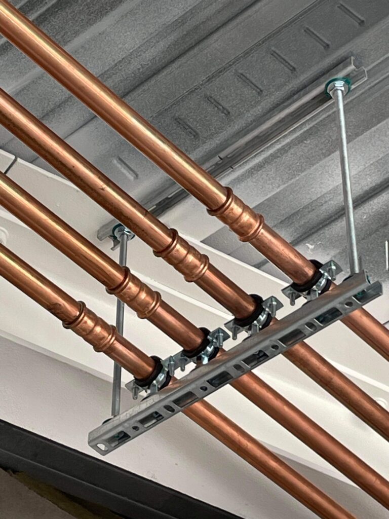
Whenever water is heated or cooled, its volume and density change. In a closed system, this translates directly into extreme pressure fluctuation, unless the expansion is safely absorbed.
In heating and cooling systems, the combination of thermal expansion and static head can easily drive pressures beyond design limits if not correctly controlled. This risks damage to pipework, fittings and other critical equipment.
In traditional sealed systems, expansion equipment provides a compressible ‘cushion,’ so that volume changes are managed without excessive pressure rise, keeping the pressure within acceptable operational limits.
Different configurations experience expansion in different ways. A low‑rise residential system with a ground‑floor plantroom behaves very differently from a high‑rise commercial building with rooftop plant, where elevation changes cause large variations in static pressure, between the lowest and highest points of the system and the knock-on effects on the vessel efficiency.
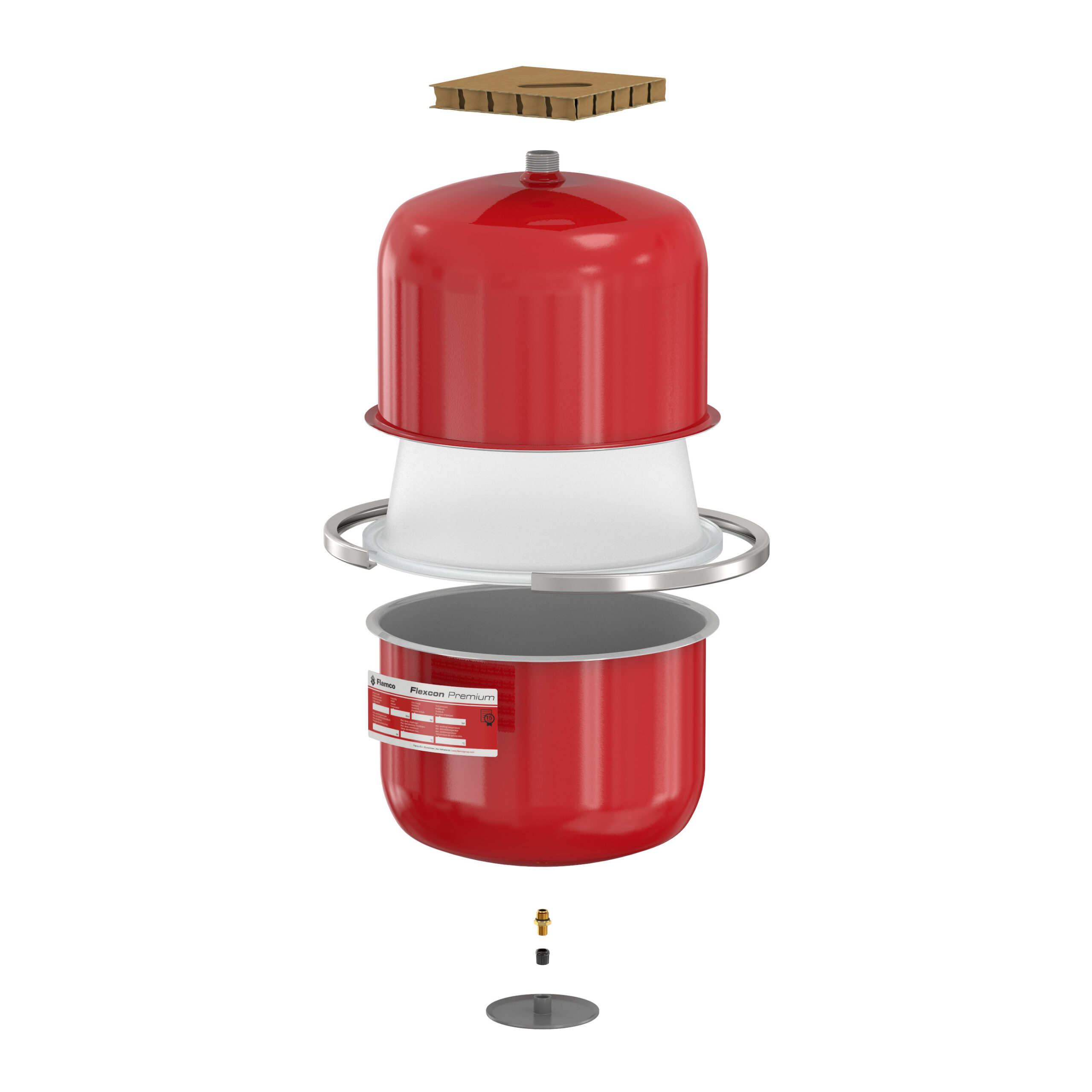
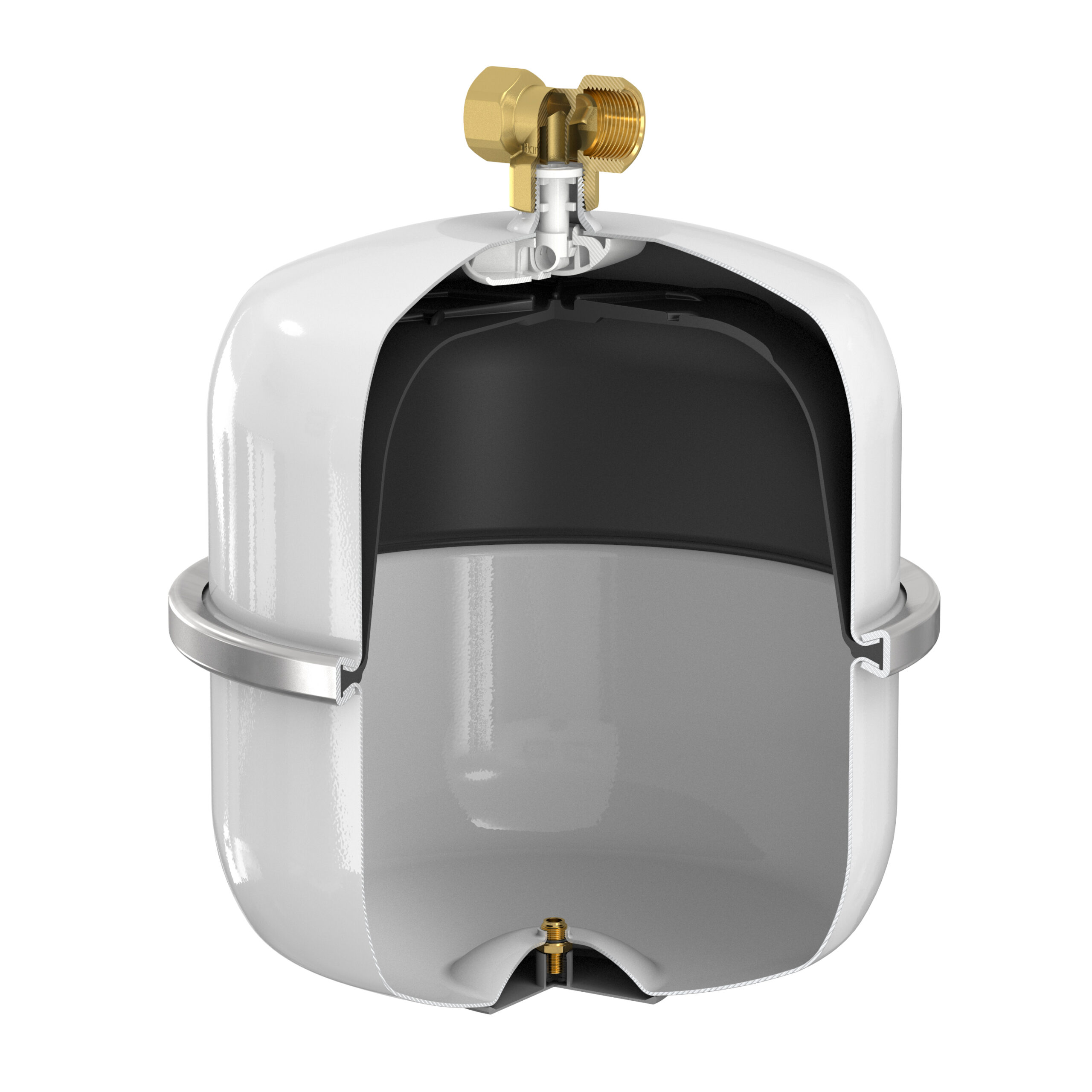
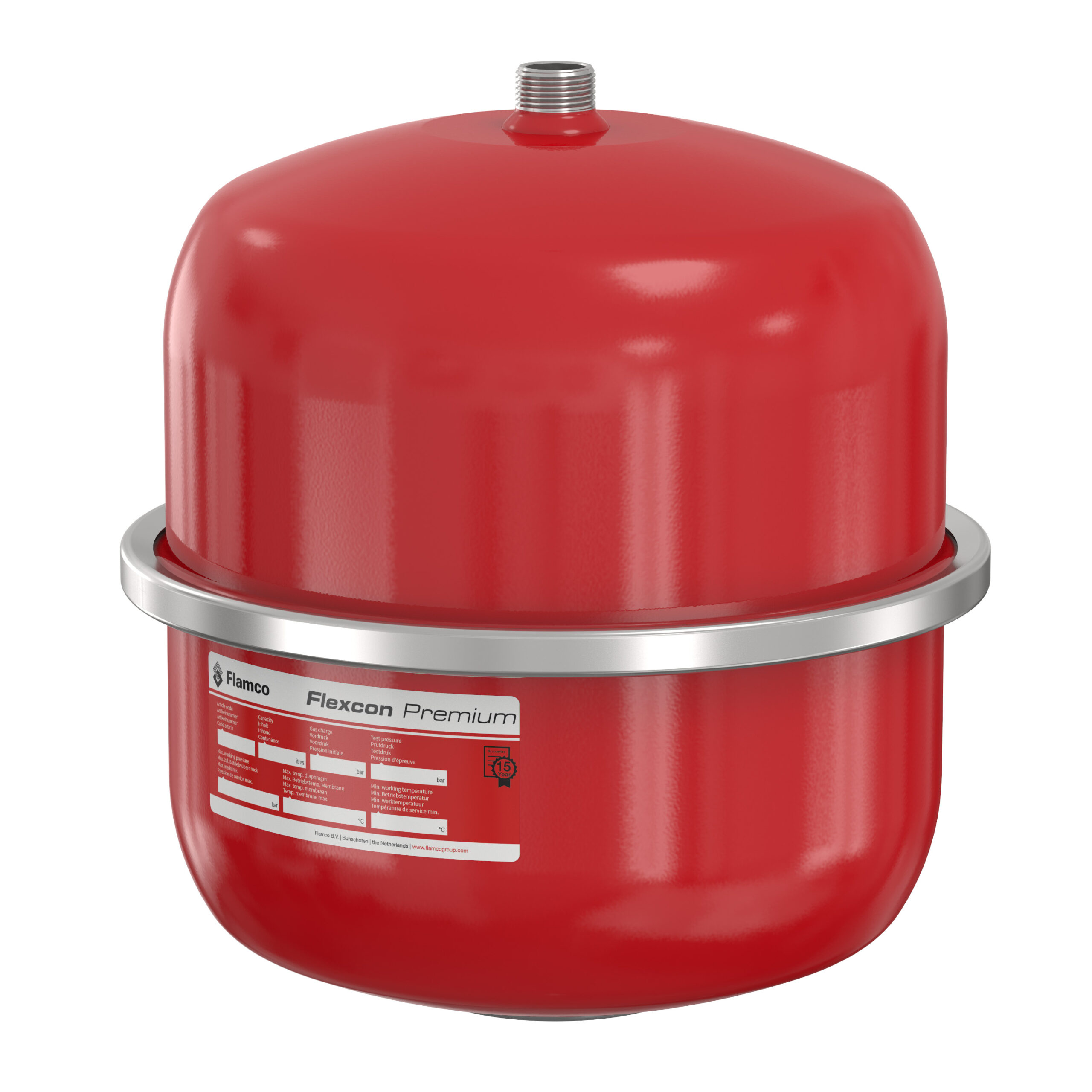
In sealed heating and cooling systems, diaphragm or bladder‑type expansion vessels are widely used to accommodate thermal expansion. Typically, these are made up of a steel shell with a flexible membrane which separates the system water from a pre‑charged gas space. As the system heats up and water expands, liquid enters the vessel and compresses the gas cushion, which then returns as the system cools.
Configurations include fixed‑gas (diaphragm) vessels and bladder vessels with replaceable membranes, offered in various orientations and connection arrangements to suit different requirements.
The choice of vessel type is influenced by operating temperature, system pressure, required acceptance volume and service expectations. Larger or more demanding installations may use packaged expansion control units to maintain tighter pressure control, than ‘passive’ vessels alone can achieve.
Potable water systems require a different approach because water quality and hygiene must be maintained alongside pressure control.
In unvented hot water cylinder systems, cold potable water is stored and heated in a sealed environment. The resulting thermal expansion must be absorbed locally to avoid nuisance discharge from safety devices or unwanted back‑pressure onto the supply.
Potable expansion vessels are therefore installed downstream of check valves and pressure‑reducing valves, with internal materials and construction suitable for wholesome water.
A key development here is the “flow‑through” potable vessel design, where the connection and internal arrangement promote continual movement of water through the membrane zone during normal operation, minimising stagnation and helping to preserve water quality.
Correctly sizing an expansion vessel is essential to keep the system within its design pressure limits across the full operating temperature range.
An undersized vessel leads to excessive pressure rise during heat‑up, frequent operation of the Safety Relief Valve and accelerated wear on components. This causes inefficiency and potential system problems. An oversized vessel is inefficient in both space and cost and may indicate that the design parameters have not been properly optimised.
The design objective is to provide sufficient acceptance volume so that maximum system pressure remains below the maximum allowable working pressure, while the minimum pressure at the highest point of the system stays above the threshold needed to avoid air ingress and NPSH (Nett Positive Suction Head) pump cavitation.
This demands more than a simple “rule of thumb.” System water content, temperature range, static head, vessel efficiency and permissible pressure range must all be considered together, as one overall ‘ecosystem,’ working together.
The factors that affect vessel sizing can be grouped into six broad areas.
First, thermal expansion of the system fluid depends on the temperature range. Higher flow temperatures and wider differentials generate greater volume change that must be accommodated.
Second, static head arising from the vertical distance between the vessel connection and the highest point of the system defines the cold fill pressure required to maintain adequate pressure at the top of the system.
Third, maximum permissible pressure is set by the Safety Relief Valve and by the lowest pressure rating of any connected component, and this is not necessarily the same as nominal maximum working pressure.
Fourth, vessel efficiency is governed by the relationship between pre‑charge pressure, minimum system pressure and safety valve setting; poor selection of pre‑charge can reduce usable acceptance volume even when the nominal vessel size appears generous.
Fifth, fluid composition. Is it 100% water, or is there a glycol mix being used? The effects on the expansion rate are dramatic.
Finally, a realistic estimate of total system water content, which includes pipework, coils, heat exchangers and plant, is essential as it directly drives the expansion volume to be absorbed.
Safety Relief Valves are central to the safe operation of sealed systems and must be considered alongside expansion equipment from the outset. Typically installed at or near the point of highest pressure (often at the heat source), the valve is set to open at a defined Maximum Permissible Pressure that protects the weakest pressure‑rated component, while still allowing an adequate working margin for normal expansion.
Generally, Safety Relief Valves use a calibrated spring‑loaded mechanism to hold the valve closed until system pressure exceeds the set point, at which point it opens and discharges fluid to a safe location, limiting any further rise in pressure.
Correct orientation, design of discharge pipework and regular functional checks are all essential to ensure that the valve operates reliably. System designers should be sure that vessel sizing, pre‑charge and Safety Relief Valve setting work harmoniously to keep pressures within the designed envelope and that routine system operation does not cause repeated lifting of the valve, which is a clear warning sign that the expansion provision is inadequate or incorrectly configured.
There are explicit formulae when sizing expansion vessels. The basic relationships link expansion volume to system water content, the temperature‑dependent coefficient of volumetric expansion and the usable pressure range defined by cold fill, pre‑charge and safety valve setting. From these, the required acceptance volume and hence vessel size can be calculated, with appropriate safety margins and allowances for future extension of the system.
Manual calculation, however, can be time‑consuming and exposed to input errors when multiple iterations are required. To support good practice, some manufacturers, such as Aalberts Hydronic Flow Control, provide calculators or selection software. Used alongside hand calculations and engineering judgement, these tools can streamline design work and provide useful cross‑checks when conditions or parameters change.
Expansion equipment is not an accessory to be added at the end of a design; it is a core element of safe, reliable and efficient hydronic and potable water systems.
Correctly specified vessels, appropriately set Safety Relief Valves and, where necessary, well‑designed intermediate vessels together ensure that systems remain within their design pressure limits throughout their operating envelope.
By understanding the underlying hydronic principles, recognising the distinct requirements of sealed heating/cooling compared with potable systems, and applying sound sizing methods supported by appropriate calculation tools, many of the performance and maintenance pitfalls commonly associated with poorly controlled expansion can be avoided.
In an industry increasingly focused on resilience, safety and whole‑life value, giving expansion technology the attention it deserves is a straightforward way to raise the standard of system design.
Rob Clemson is author of the BSRIA Guide BG82/2022, ‘Pressurisation of Closed Heating and Cooling Systems’