David Rhodes, Technical Manager
Albion Valves
Delivering reliable water supply in high-rise buildings
Distributing water around high-rise buildings poses several challenges for designers and installers. It is vital to maintain even distribution of water to all floors and this means overcoming several challenges.
First, they designers must consider the force of the static head pressure created by the water within the pipework system. Static head is the height difference between the water source and the point of use.
Due to gravity, for every 1m change in building height, the pressure changes by approximately 9.81kPa. So, as water travels up the building, the pressure decreases by 9.81kPa per metre.
Designers must also consider pressure drops created as the water travels through bends and valves. The pipework also causes frictional losses. These pressure drops must be considered when sizing the pipework, as it cannot be based on the pressure delivered from the initial source.
Furthermore, in many high rise buildings, the municipal water supply pressure is not adequate to meet the requirements of the water distribution system. UK water authorities are obliged to supply water at a minimum of 0.7 bar (70kPa) which equates to roughly 7m head (height) of water.
This water pressure decreases against the geodetic height of the building to such an extent that it is only sufficient to provide water to 2 storeys. Tall buildings must therefore have a ‘pressure boosted water distribution system’, achieved through the use of pumps.
These pumps, typically located in the building’s basement or a dedicated pump room, elevate the water pressure to ensure it reaches the upper floors of the building. However, while pumps solve one problem, they can also create another because they significantly increase water pressure in the pipework, particularly at the lower floors.
This can cause issues for the occupants such as noisy pipework due to excessive vibrations caused by cavitation or water hammer, or faster deterioration in valve seals causing terminal units to be replaced more frequently.
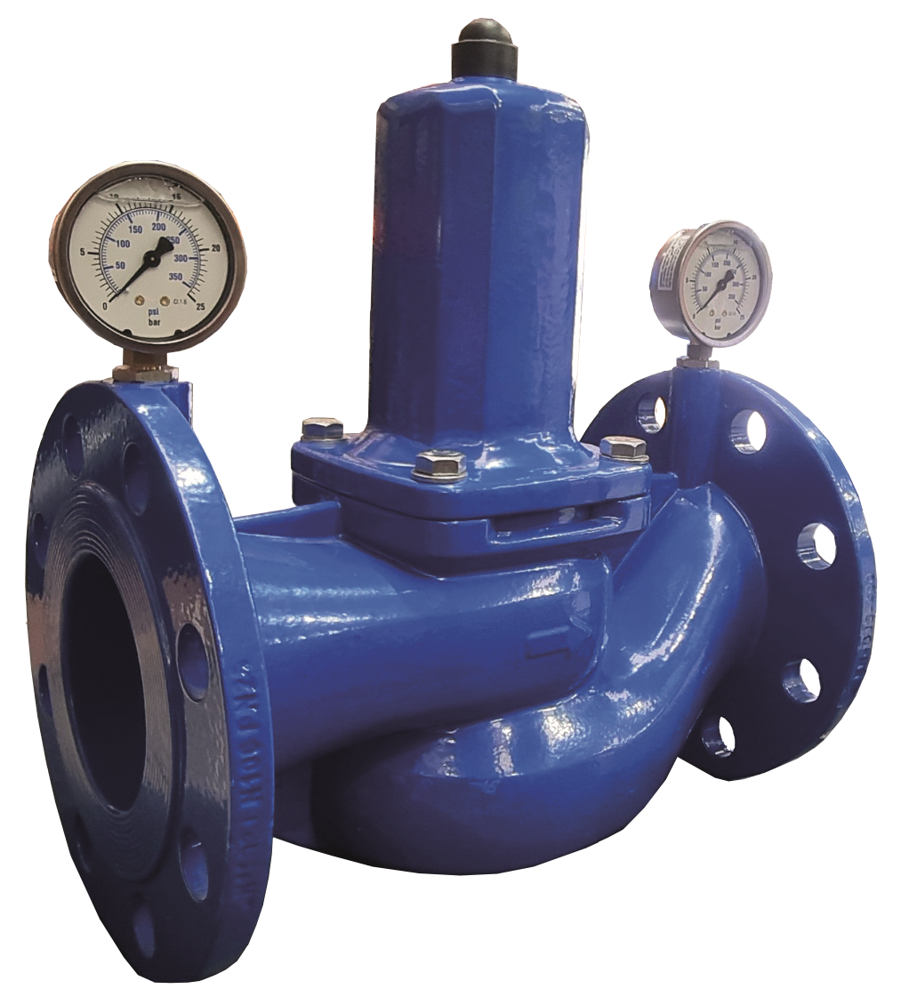
Pressure reducing valves (PRVs) can resolve issues of excessive pressure. But they must be sized and applied in a way that is appropriate for the building’s requirements.
Water systems must comply with the current UK Building Regulations, which limit the designed daily water consumption. Some designers currently size pipework based on full flow conditions in which they assume that every outlet such as toilets, sinks and showers will always be in operation. This can lead to oversized pipework. Instead, water distribution systems should be calculated using loaded units.
According to the Chartered Institute of Plumbing and Heating Engineering (CIPHE), loaded units can be defined as: “The loading units (LU) within BS EN 806-3 take into account the flow rates at the draw-off point, the length of time the appliance is in use and the frequency of use. One loading unit (1 LU) equates to a draw-off flow rate QA of 0,1 l/s.”
These loaded units, in combination with a series of pipework tables, can help designers calculate the correct pipe size required.
PRVs are designed to restrict pressure as the water moves from the valve inlet across the valve to the outlet port. It does this by passing the water across a spring and diaphragm arrangement that creates a resistance, lowering the pressure to a manual pre-set determinate level, which can be verified by the gauge.
Regulating the water flow to a specific pressure eradicates sudden spikes in pressure as the spring and diaphragm respond to the changes in upstream pressure. This maintains a more constant downstream water supply, adding additional protection to any downstream pipework or equipment.
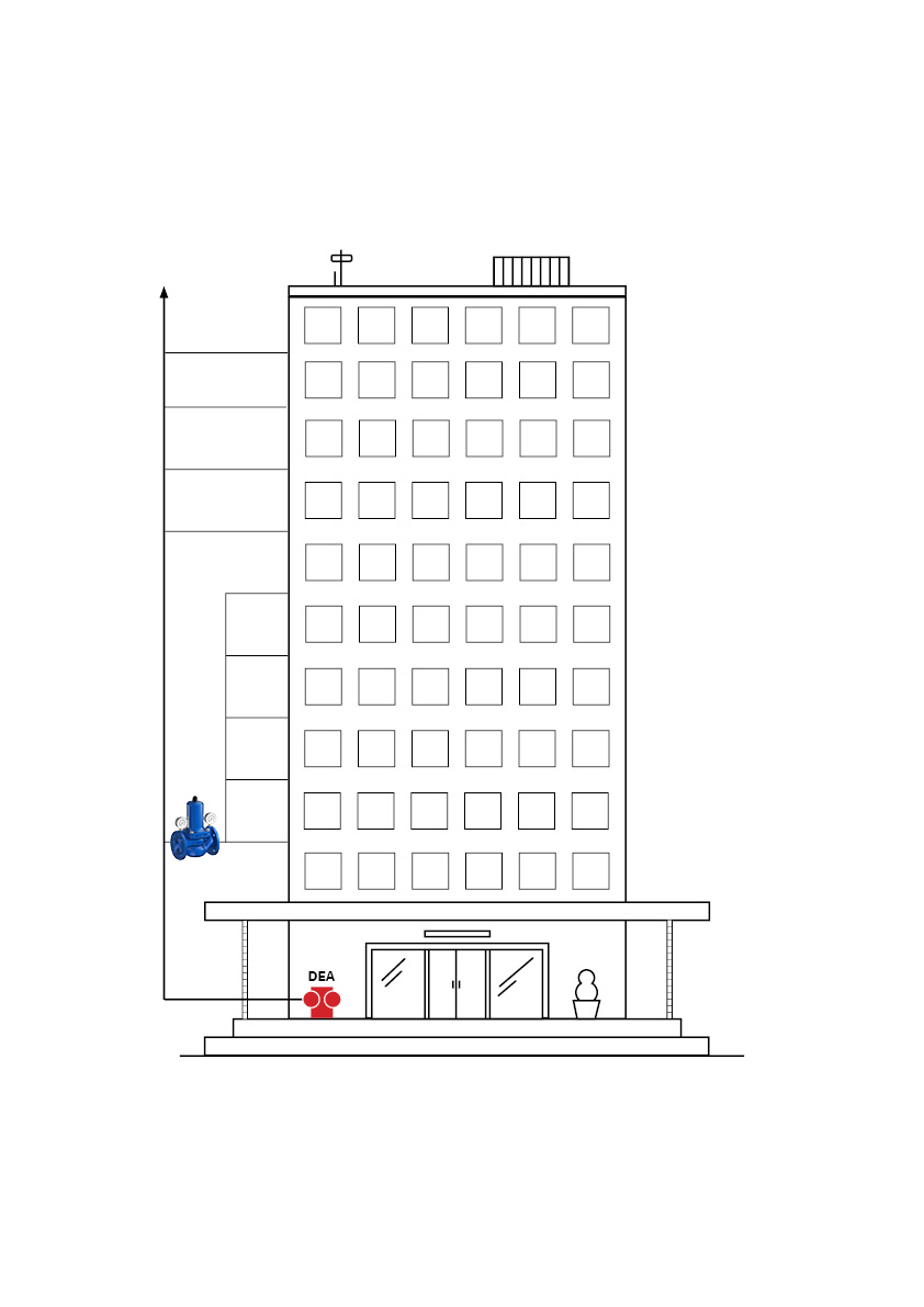
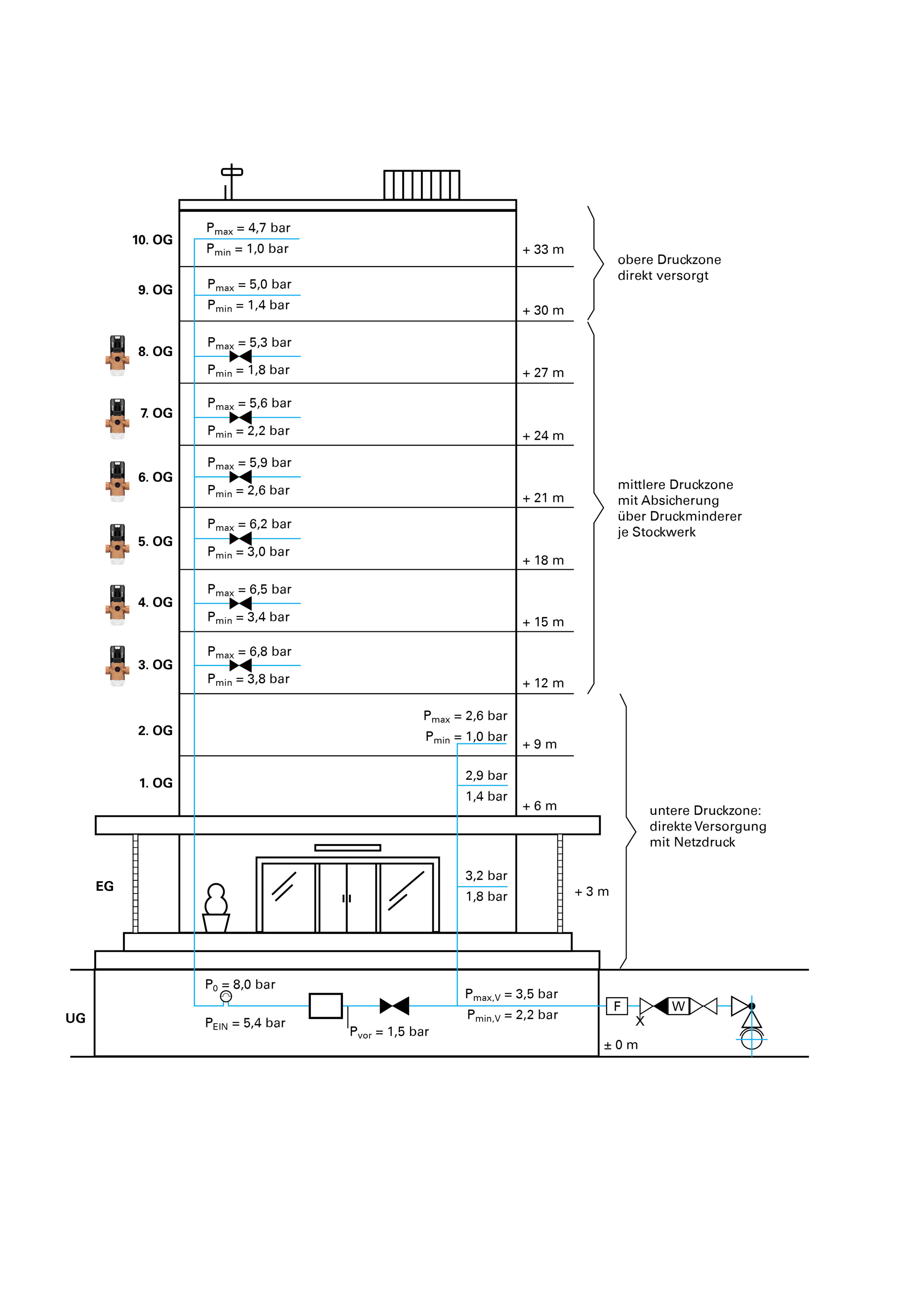
The design of water distribution systems using PRVs in tall buildings can be summarised into three main approaches. Figure 1 shows a building divided into pressure zones. Here, several floors are protected collectively via a pressure reducer.
In this case, PRVs are placed on the lower level of the zone and set to a high-pressure range. This type of installation is a cost-effective solution but has the disadvantage in the event of maintenance that the individual zone must be supplied with emergency pressure during this period and the pressure control takes place in a much wider spread area.
Figure 2 uses a floor-by- floor approach. Each floor that requires water pressure reduction is equipped with its own pressure reducer. Each PRV can then be adjusted individually, achieving optimum water pressure for each floor, flat or office.
Although there are higher capital costs for more PRVs, the benefits of this approach are that supply of water to all floors is guaranteed in case of maintenance, as well as optimising water consumption.
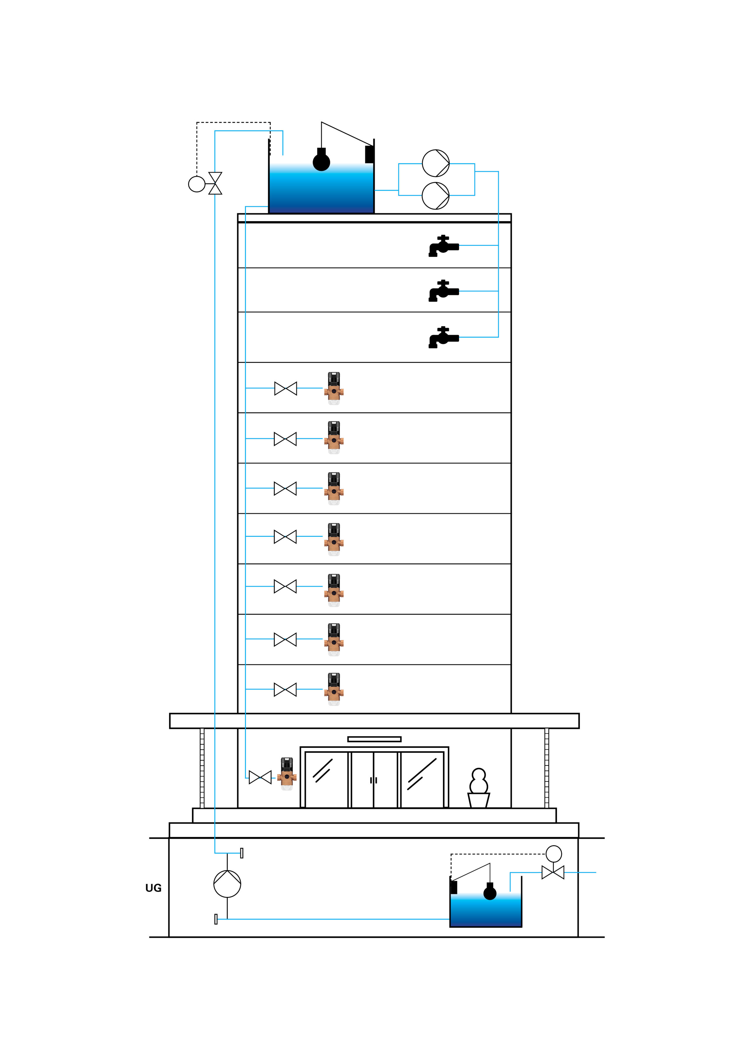
A third option, shown in Figure 3, is to use a reservoir. The water is pumped into an elevated tank on the roof of the building to be supplied. The water then flows by gravity to the individual floors that are too high to be adequately supplied with the urban pressure.
However, the floors supplied with this top-down supply model have the opposite problem on the lower floors, as the water pressure increases with each floor downwards due to the geodesic height. So while the water pressure is sufficient on the upper floors of a tall building, there is usually too much pressure on the lower floors.
As high rise buildings become more prevalent in our cities, it’s vital to think about the correct designer of water distribution systems, and to ensure the best application of PRVs for each building.

